

Vette
Sounds Classic American Issue 161 |
|
|
For a lot of people Chevrolet's C5 Corvette was a
natural progression from the C4, after all 5 does come after 4. The
sleek lines, stunning interior and Chevrolet's new 5.7 litre power plant
moving everything along, what could be better? Well the sound many of
you will be calling out, and this is meant in more ways than one. To
start with not all C5's left the factory complete with a CD changer.
Not a big problem, but for those of you who want your favourite tunes
whilst cruising, a damn inconvenience. Secondly for those of you who
love to hear the raw power of a V8 then the C5's stock exhaust leaves
a lot to be desired. Read on and learn how to rectify both of these
dilemmas.
For those of you who would like to install a CD changer in your C5 Corvette, it's not as big a task as you might first imagine. With the exception of the changer itself and the cable, you already have everything you need in the vehicle. The Delco-Bose head unit, see fig 1, is already geared up to use a CD Changer, so all you need to do is choose one. For that authentic touch you may opt for the Bose changer. This is a 12 CD unit and is the same as the factory option. The other popular and often cheaper option is to use an after market brand such as Kenwood. To connect your changer to the head unit you will need the appropriate cabling. If you choose the Bose option you will only require the cable shown in fig 2. However if you choose to use a Kenwood changer you will also need to use an adapter cable to run the unit, see fig 3. |
|
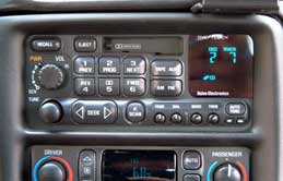 Fig 1. Delco Bose head unit. |
|
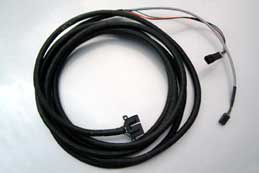 Fig 2. Bose CD changer cable. |
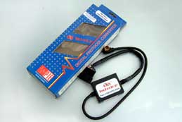 Fig 3. Adapter cable for Kenwood changers. |
|
On to the installation. The first thing you would
expect to do is pull out the head unit, but in a word DON'T. The two
small connectors you are searching for reside, not behind the all-elaborate
Delco-Bose unit, but in the passenger foot-well, see fig 4.
You will need to pull back the carpet and insulation. To make this job a little easier, you may want to remove the panel at the front of the foot-well. This exposes not only the wiring loom that you need but also the vehicle's computer. Again see fig 4 to clarify this. The wires and connectors will usually be found taped into the loom running just below the plastic kick panel located on the right of the foot-well. Next job is to plug in the two small connectors and tape them back into the loom to keep things tidy. Once connected, route the cable to the rear of the vehicle. This is best done along the bottom of the door opening, below the wrap over sill plate. Run the cable along the inside of the right hand rear quarter, see fig 5. Then run it behind the cover for the rear lamp cluster. |
|
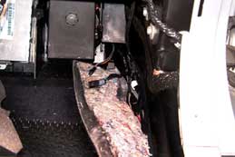 Fig 4. Cable connectors in the footwell. |
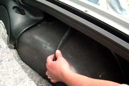 Fig 5. Route the cable to the rear of the car. |
|
The cable should easily be long enough to reach the
large rear storage compartment. This compartment is probably the most
suitable place to mount the CD changer.
But slow down, before you go rushing out to buy a new Kenwood changer you should note that not all of the Kenwood range are compatible with the Delco-Bose head unit. However once you have the cables installed, take a trip to you friendly audio centre and they will hopefully steer you in the right direction. They may even allow you to try a unit before you purchase. Once you have your changer it is just a matter of mounting it to the back of the large storage compartment using the fixing kit supplied. See fig 6 & 7. You should now be ready for miles and miles of pure audio ecstasy. |
|
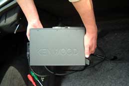 Fig 6. Mount the changer in the storage box. |
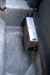 Fig 7. Finished, Job well done. |
Moving
onto the exhaust, what can be said about the stock C5 system? It does
its job in a bland unobtrusive way, and that's about it, See fig
8. Whilst the C5's looks certainly make it a real head turner
its sound does not. This is easily remedied by the replacement of the
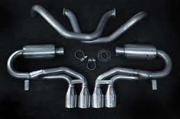
stock system with a tasty stainless steel after market system. In this
case the system of choice is the 'new' Borla "Stinger". Made
from 304 stainless steel with free flowing silencers, polished 4 inch
angle cut rolled tips, and boasting a 9-12 horsepower increase, see
fig 9. And as we all know a few extra horses is never
a bad thing. |
|
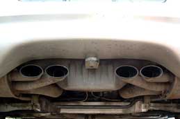 Fig 8. C5's Stock system. |
|
|
This job is obviously easiest if you have access
to a hoist or ramps, but don't let this put you off, it's amazing what
can be achieved with a trolley jack and axle stands. Just think of yourself
as the Jamie Oliver of the car world and make the most of what you have
to hand. The first thing to do when fitting anything new is to unpack
all the new shiny parts and compare with what is on the vehicle. Check
to make sure the flanges look the same and that the over axle pipes
look similar to the ones already on the car. Once you are happy that
everything looks like it is going to fit, remove the old system. If
you wish to keep this you may find that you need to loosen the rear
sway bar to remove this in one piece. However, if you just want to get
your new system on, then the best solution is to take a hacksaw, or
some other type of rudimentary cutting device, to the over axle pipes
just behind the axle assembly, see fig 10.
Once you have cut through the over axle pipe you will need to undo the two bolts on the flange that is just in front of the rear axle, see fig 11. Once done you should have little difficulty in removing this short section of pipe. Do what you like with this, as it is no longer required. Moving to the remaining rear section, you will need to remove and retain the silencer hanger. This is located up between the rear valence and the silencer itself. The easiest way is to use a socket on a fairly long extension here. You may be able to use a spanner but there is not a lot of room up there. After removing both bolts the hanger, silencer and remaining pipe work can be lowered with little or no trouble. You now need to repeat the procedure for the other side of the vehicle, leaving you with a Corvette with no exhaust from the cat back. |
|
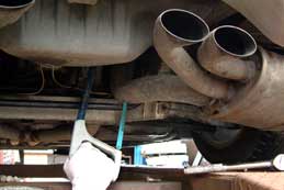 Fig 10. Cut the over axle pipe. |
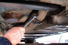 Fig 11. Unbolt the flange. |
It is
often said that preparation is the foundation of a good job, and that
is true enough here. A little time spent cleaning the flanges will reduce
the chances of an exhaust leak once the system is together. Scrape any
old gasket material away, see fig 12, and then wire
brush the surfaces until you are happy there are no small pieces of
debris that could potentially cause a leak, see fig 13.
It is time to yet again unpack your new system. |
|
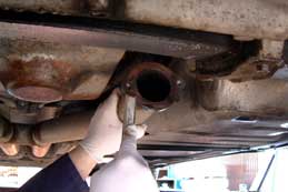 Fig 12. Scrape the flanges |
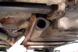 Fig 13. Just to make sure, wire brush as well. |
Starting
with the over axle pipes, slide them into place. You may find you need
to rotate them slightly to help guide them through such a tight space.
Fit the new gaskets and just finger-tighten the bolts, see fig
14. You may find that an extra pair of hands will come in useful
for the next part. Fit the old hanger to the new silencer and offer
up the silencer section and slide it on the over axle pipe. Make a note
here not to forget to slide the one-piece clamp on, as this cannot be
fitted later like a conventional clamp. Raise the silencer assembly
and locate the hanger into place. You should be in a position now where
you can stand back and get an idea of what the finished job will look
like, see fig 15. |
|
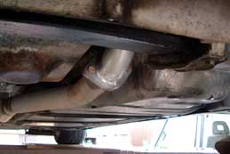 Fig 14. Fit new gaskets and bolts |
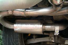 Fig 15. Everything is roughly in place. |
The
two piece design of the Borla system allows you a great deal of adjustment,
so you can get the tips of the system aligned exactly how you would
like. Once you have aligned the system how you want it, simply tighten
the clamps to seal the joint between the silencer and the over axle
pipe, see fig16. Then tighten the hanger, remember
the one between the rear valence and the system, see fig 17.
Check the tip alignment again, and as long as you are completely satisfied,
tighten the flange bolts. You shouldn't need to use and chemicals on
the joints, but if you would rather be safe than sorry, then just a
smear of exhaust paste should be all that's required. There you have
it, job done, fig 18. |
|
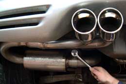 Fig 16. Tighten the clamps. |
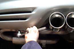 Fig 17. Tighten the hangers. |
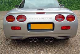 Fig 18. Job Done |
|
Now
for the moment of truth, turn the key and listen to what will sound
like a completely different car. When choosing your system it is best
to talk to as many people as you can about what's available and they
way each system sounds. Each has its own little nuances and characteristics,
however, if it's a strong but controlled sound you are looking for,
you can't go too far wrong with the Borla Stinger. Best advice here
is to talk to your spares supplier, ultimately the choice is yours but
they should be able to point you in the right direction. |
|