

Bright
Sparks Classic American Issue 163 |
|
At some time during a lifetime of driving we will all suffer the inevitable ignition failure. It is almost guaranteed to happen either late at night or first thing on a frosty January morning. You turn the key and then one of two things happens: either the engine turns over without any sign of ever starting, or your vehicle starts but runs as though its been tuned by a chimp. Either way the chances are you're stuck. So what is the next move? Read on to get an insight on what makes your car or truck run, and how to diagnose some of the more basic ignition system faults. Obviously there are several different types of ignition system. For example, single and dual point, distributor based electronic and distributorless. Just to make things even more interesting each manufacturer has their own version of these systems. Whilst the principles behind each system remains pretty much the same, for this article we shall be concentrating on the breaker point ignition systems. So let's run through the circuits pointing out some things to look out for and how to diagnose some simple faults. The basic ignition system is actually made up from two circuits. The primary circuit and the secondary circuit, The primary circuit is a simple low voltage circuit. This circuit carries current at battery voltage, usually 12 volts on most modern systems and 6 volts on most older and vintage vehicles. The following items are usually found in the primary circuit: the battery, ignition switch, starter relay, ballast resistor, primary coil winding, either a single or dual set of points, a condenser and finally a ground. The ballast resistor is used to modify the current in the primary circuit for use in the ignition system. More about that later. The secondary circuit is high voltage beginning with the secondary windings of the coil. The voltage created here, in a stock coil, can be as high as 30,000 volts. In some performance applications this could even reach 50 or 60,000 volts. Once this voltage leaves the coil it flows down the high-tension lead to the distributor cap. From here the rotor arm ‘distributes’ the voltage, via the cap and plug leads, to the spark plugs and finally to ground. As you can see from this simple explanation there is not a lot that can go wrong in a points based system. However, if something does fail you will want to know how to find the problem and then how to put it right. As with any fault diagnosis a simple methodical approach is best, take things one step at a time. Firstly, you should carry out some simple visual checks. The majority of system failures on points systems are through some kind of physical damage to a component part of the system. Start with the cap; check all the metal terminals both inside and outside the cap for signs of burning and corrosion. Also check for any cracks in the cap. Fig 1 shows two caps, the one on the left is new. Notice all the terminals are clean, the centre electrode is not burnt and there are no cracks. However, the cap on the right is not as healthy, notice the crack in the wall, indicated by the arrow. Also notice the burnt and blackened terminals, this cap would certainly require replacement. Next check the rotor arm, again if there is any physical damage it is best to replace the item. The rotor in fig 2 has extensive burning on the tip and top terminal; therefore it should be replaced. Next carefully look at the points, check the contact areas for signs of pitting or burning, finally make sure the points are opening and closing freely. |
|
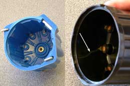 Fig 1. Check the cap. |
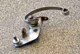
 Fig 2. Check the rotor arm. |
Again
if there appears to be any problems here, simply replace the points.
Fig 3 shows a badly pitted set of points, a vehicle fitted with points
in this condition would certainly have running problems. Pitting of
the points can be caused by a faulty or incorrect condenser or a resistance
problem in either the primary or secondary circuits, again more on this
later. Next thing to check is the plug wires. These are an often over
looked part of the ignition system, however, if they are not in prime
condition the ignition system will not function correctly or it will
fail completely. Start by checking each leads jacket for splits and
burn marks, if you find any this is a sure sign that the lead has been
tracking to ground. Check the lead boots as well; making sure that they
are all secure and all the terminals are clean. Do not try to scrimp
and save when it comes to leads, if one lead has failed in some way,
simply replace the set. Individual lead replacement can be false economy
in the long term. Fig 4 shows two leads the top one is new, however,
the bottom one has splits in the jacket and boot. There is only one
place for leads in this condition, the bin! Checking the spark plugs
should be a regular part of any service, but again they often get over
looked, so as with the rest of the parts, if in doubt throw them out.
The final part of the visual inspection will be the ballast resistor.
Again look for any physical breaks in the item and any signs of burning.
At only £3 to £4 for a stock resistor, it’s usually
worth changing this just in case you suspect any problems. |
|
|
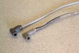 Fig 4. Old and new lead |
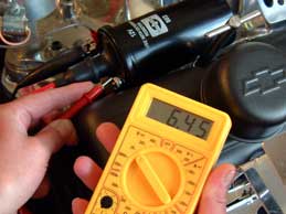
| With the visual checks out of the way, if you still have problems it’s time to get the multimeter out and carry out some voltage and resistance tests. If you don’t have one of these meters they are readily available from various DIY and tool outlets, and do not have to cost a fortune. Let’s start with a check on the primary circuit. If possible get the engine to its normal working temperature and switch it off. Now run a jumper wire from the distributor side of the coil to ground. Then wire the multimeter, set to read voltage, between the ignition switch side of the coil and ground. Now with the ignition switched on, DO NOT TRY TO START THE ENGINE, just wriggle the key in the switch. If the meter reading fluctuates rapidly this is a good sign that the ignition switch is faulty. Obviously it’s a good idea to replace the switch and the barrel with key. If the switch is all right move on to check some voltage readings in the circuit. With the ignition in the ‘on’ position, the meter should read between 5.5V and 7V on a 12-volt system, see fig 5. Now try to crank the engine over, whilst the engine is turning over the meter should read a minimum of 9V, see fig 6. | |
|
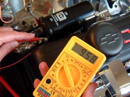 Fig 6. Meter should read a minimum of 9V. |
Now
remove the jumper wire from the distributor side of the coil. If possible
start the engine; the meter should now read between 9V and 11.5V depending
on the output from the alternator, see fig 7. If the readings from these
tests are not what were expected, don’t panic. We are making progress
and will eventually solve the problem. |
|
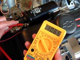 Fig 7. Meter should read between 9V and 11.5V. |
|
We should
now move on to check the ignition coil. The easiest check here is to
take simple resistance readings of the primary and secondary circuits.
To check the primary side of the coil, set your meter to read ohms on
a low scale, probably 0 to 200 ohms. Then connect the meter leads to
the primary terminals of the coil. On a 12-volt system you should get
the following results. For coils that require an external ballast resistor
in the primary circuit, the meter should read approximately 1.0 to 2.0
ohms, see fig 8. On coils that do not require an external resistor,
the meter should read approximately 4 ohms. If the readings are dramatically
different from this, it may be a good idea to try replacing the coil. |
|
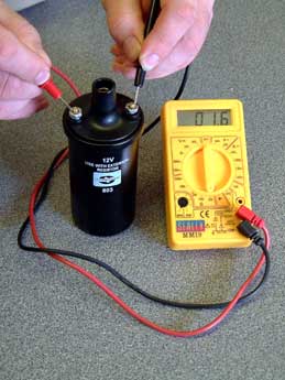 Fig 8. Meter should read 1 to 2 Ohms. |
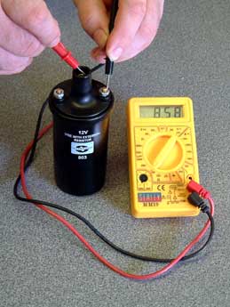 Fig 9. Meter should read 4K to 9K Ohms. |
|
On nearly all 12-volt points systems, some form of
ballast resistor is used in the primary ignition circuit. This may be
built into the coil, it may be a resistance wire or an actual resistor
mounted externally to the coil. Whichever resistor your vehicle has
it generally serves two purposes. Firstly it limits the current that
flows through the coil and the contact points. This helps to protect
the points at slower engine speeds. This is when the points are closed
for the longest period and are prone to burning out if they receive
excessive current. Secondly, the ballast resistor also protects against
excessive build up of current in the primary circuit when the ignition
is switched on, the points are closed and the engine is not running.
The easiest way to check the resistor is visually as was mentioned earlier.
It is now time to move on to the distributor side of the primary circuit, or to put it simply the points and condenser. Set your voltmeter to read on the low scale, 0 to 20 volts. Now connect one lead to ground and the other lead to the distributor side of the coil, also remove the high-tension lead from the coil and ground it. You may need to enlist the help of a friend here, or grow a third hand whichever is easiest. With this done just briefly turn the engine over. The meter reading should be any thing from one-third to one half the battery voltage, see fig 10. Here we are showing a reading of 4.77 volts, just over one third of the battery voltage. As a further test, with the points open and engine stopped the meter reading should be the same as the battery voltage, see fig 11. Conversely with the points closed and engine stopped the meter reading should be very close to zero, see fig 12. |
|
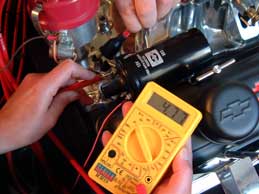 Fig 10. Showing 4.77 Volts. |
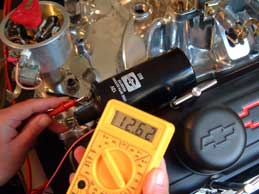 Fig 11. Meter showing battery voltage. |
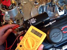 Fig 12. Meter should read close to zero. |
|
|
If the reading you
took whilst turning the engine over was zero or very low, then you have
one of the following faults:
1. The points may not be opening correctly due to incorrect adjustment or some kind of mechanical failure either with the points themselves or the distributors cam. Obviously if you have a dual point set-up, it may be either one of the sets failing, or in an extremely unlucky case both sets. 2. There is no voltage at the distributor. Testing for voltage at the distributor terminal of the coil easily checks this. 3. The condenser pigtail or the distributor primary wire terminal is grounded. 4. The condenser has what is known as a dead short. You can check this using your ohmmeter. Connect one lead to the case of the condenser and the other to the small pigtail lead. If the meter shows any reading at all then the condenser needs to be replaced, see fig 13. |
|
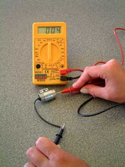 Fig 13. This condenser needs replacing. |
|
A condenser that is either shorted or open will obviously not function correctly. If the condenser is under capacity for the system then this will cause the stationary contact, of the points set, to breakdown and pitting will occur on the stationary contact. The opposite will happen if the condenser is of too high a capacity, causing the movable contact to pit. If you have read this far and feel that points are really more trouble than they are worth, then you do have some options. Probably the simplest option is to replace the points and condenser with one of the many electronic conversion kits that are available. The Pertronix conversions are extremely popular at the moment, and with prices starting at about £70 or £80 they are not too expensive. You may find that you will also need to change the coil when making this conversion. If you are not sure you can always ask your friendly parts supplier, they should be able to let you know exactly what you require. If you would rather lose that old distributor completely, then there are some very nice after market breakerless distributors available. The most popular being made by Mallory and Accel, but expect to pay two to three times the price of the conversion for these, although other companies such as Proform are also making some very good replacement distributors now. These tend to be more competitively priced. So to sum up, a points
system can be maintained very easily. Fault diagnosis is very straight
forward, using only very basic equipment, the parts aren’t terribly
expensive and they are relatively simple to fit. However, if you feel
you need a change there are some options open to you. These too are
relatively inexpensive and straightforward to fit. So next time your
points system gives up, don’t do the same, just dig out your multimeter
and you’ll be up and running in no time. |
|