


Frame
of reference Classic American issue 182 |
||
So here we are, about
to embark on the final part of our journey through the various chassis
components. It is only fitting in that case to end with the chassis
itself. It is, as many of you will already know, in essence the framework,
the skeleton, and the backbone of virtually every car, van, pickup
and truck. It is the part of the vehicle that everything else is connected
to. There are many different types of chassis, the monocoque, the
ladder frame, the tubular space frame, the backbone and many more.
However, the two styles of chassis we shall be concentrating on primarily
are the monocoque and the ladder frame. These two designs are probably
found in more vehicles than any other. |
||
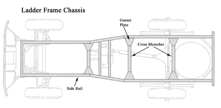 Fig 1 |
||
With a chassis design such as the ladder type, the body only has to be strong enough to take the weight of the cargo and resist any dynamic loads associated with cargo handling and movement. The body, in certain designs, will also be subjected to some torsional loads that are not completely absorbed by the chassis frame. However, this mainly applies to heavy trucks and not so much to passenger vehicles. For those of you who like to get into number crunching you may like to note the following. In the average passenger car with a ladder type chassis, the frame accounts for 37% of the torsional rigidity and approximately 34% of the bending rigidity; the rest is supplied by the structure of the body. Obviously there are a number of advantages to be had in having separate chassis frame and body. Firstly there is the ease with which the body can be mounted and dismounted. This in turn leads to better isolation of noise from the drive train. This is achieved through the use of rubber or urethane mounts between the frame and the body. The simplistic design of separate body and chassis often allows for a relatively inexpensive and easy manufacturing process. This in turn can lead to extreme versatility; in as much as various body designs can be adapted to fit a single common chassis type. This approach is very common in truck manufacture. Of course the designs are exceptionally strong and rugged, however, the trade off is an increase in vehicle weight. The frame also serves as an extremely strong mounting point for items such as engine, suspension, fuel tank, spare tyre, tow bar etc… |
||
Having
spent a little time with the ladder chassis we are now moving on to
the MONOCOQUE design. NO, not black and white roosters, those of you
with a flair for languages will know this is French for single-shell.
In a way this is exactly what we are dealing with, a one-piece structure
that combines both frame and body. This unitised construction, as it
is often referred to, is achieved by either welding all the components
together or by forming or casting the entire structure as one piece.
It should be pointed out that simply welding a body shell to a conventional
chassis frame does not make that item a monocoque design. In a true
monocoque design the frame and body structure is treated as a load-carrying
member. It is this unit that reacts to all loads, be it stress, road
or cargo. Welding preformed metal panels together forms the bodies for
these integrated type designs. These panels are formed into various
load-bearing shapes that are orientated in the bodies design so as to
form a uniformly stressed structure. This results in some parts of the
integrated structure resembling frame-like components whilst others
look like body panels. This should not be that surprising as the structure
must perform the functions of both these integrated elements. This type
of design obviously has its pros and cons. The major disadvantage of
this type of construction is the amount of noise transmitted to the
passenger compartment. Because there are no rubber or urethane bushes
the amount of noise transmitted to the passenger compartment is a lot
higher than in the separate body and chassis frame design. However,
modern sound proofing techniques do help to reduce this considerably.
The advantages of this type of design do, however, out way this disadvantage.
The main advantage is the substantial weight saving. This obviously
leads to savings in other areas such as fuel economy. In trucks and
vans it is possible to have a lower cargo floor area and vehicle height.
This can be an advantage when loading and unloading cargo. There is
also the all round advantage of a reduction in structural vibration.
|
||
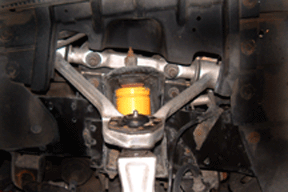 Fig 2 |
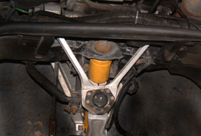 Fig 3 |
|
As
we have seen there are major differences in these two types of vehicle
chassis frame. It is, however, interesting to see several similarities
creep in when it comes to the mounting of certain components. Take the
control arms for example; as you may remember from previous articles,
the front control arms are where the lower and upper ball joints are
mounted. These control arms are usually an ‘A’ shaped frame,
hence the common British terminology of ‘A-arm’, see fig
2. fig 2 shows a typical ‘A’ arm viewed from the side, whilst fig 3 shows the same arm viewed from the top. These ‘A’ shaped arms are fitted to the chassis using a long shaft and two metalastic rubber or polyurethane bushes, see fig 4 & fig 5. |
||
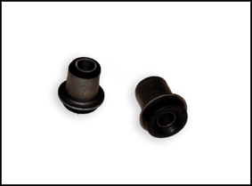 Fig 4 |
 Fig 5 |
|
.
The shafts are bolted to the chassis, see fig 6. This
as you may have guessed will be pretty much the same whether you have
a separate chassis and body or a monocoque chassis. It should probably
be pointed out here that not all front control arms are ‘A’
shaped. Take the 1960’s Mustangs for example, see fig
7. |
||
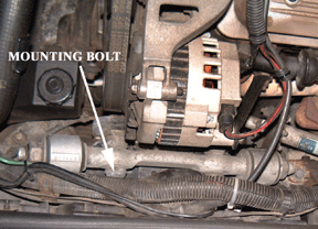 Fig 6 |
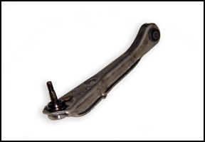 Fig 7 |
|
These
have a lower arm that is held in place by just a single bush and bolt,
see fig 8, with a trailing strut arm for location.
As always what we are trying to say here is be prepared for some variations,
various manufacturers are always trying something new, sometimes it
works and sometimes it doesn’t. Rear control or trailing arms
are also mounted in very similar ways. Usually from the axle or diff
to the chassis frame or a frame like component of a monocoque chassis,
again using a long bolt and one or two metalastic or urethane bushes,
see fig 9. |
||
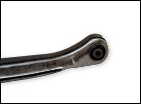 Fig 8 |
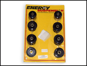 Fig 9 |
|
So
now you have a fair idea of what the chassis is, how it is constructed
and what is mounted to it. But, and there is always a but, what can
go wrong with the chassis, what should you look out for, is there anything
that can be thought of as chassis maintenance. Well because there are
no actual moving components in the chassis itself there is no need to
concern yourself with any wear problems. The chassis can be classed
as a non-wear item. There are two main enemies as far as your chassis
is concerned, one is rust and the other is accident damage. If you are
lucky enough to be able to garage your vehicle on a regular basis, then
rust is some thing you need not worry about. However if your vehicle
lives outside you should check your chassis regularly. There are of
course many things you can do to help prevent the onset of rust, either
wax oiling or under-sealing are probably the two most common courses
of action. However if you are on a tight budget simply wire-brushing
the excess rust from the frame and painting the affected area can help
slow the rust until a more permanent fix can be made. We have seen cars
where the rust has gone un-noticed, the result has been a car that gets
lower and lower….and lower. This is due to all the suspension
mounting points rusting away and allowing the frame to sink down past
those points. This is an extreme case, but it can happen and it should
go without saying that it is extremely dangerous. This kind of rust
damage will affect the way a vehicle handles at times causing unpredictable
glitches in steering or suspension response that will make the vehicle
uncontrollable.
Accident damage, in a way, can be a lot worse than rust damage in as much as it is not always visible. Sometimes it takes only the slightest knock to bend a chassis frame enough to put it out of alignment. This type of misalignment usually manifests itself as a steering defect, with the vehicle tending to pull to one side. However, care should be taken not to diagnose chassis misalignment without first having checked the steering geometry, as we have discussed in a previous article. It is possible to remove minor bends from a chassis using a chassis jig and a system of clamps and hydraulic jacks and presses. Small cracks in the frame can be repaired by drilling the frame and then fishplating the affected area. This kind of repair should really only be carried by a professional because if care is not taken the frame can be weakened. Any welding on the frame should not be carried out using gas or arc welding unless actually specified by the manufacturer. The heat from these types of welding removes the temper from the metal and if allowed to cool to quick causes the metal to crystallise. This makes that area of the frame very weak and susceptible to further damage or cracking. As just one final point,
we mentioned the mounting of the control arms to the chassis. The bushes
used in these joints should also be checked regularly. It is amazing
how many erroneous noises or steering defects can be traced back to
worn or perished control arm bushing. Likewise, if your vehicle has
separate body and chassis, you would be wise the regularly check the
bushes between the body and chassis frame, see fig 10.
Again, a large amount of noise can be eliminated by simple replacing
the body mounts. Because of the large stresses the bushes used in mount
the control arms and body are under it is often recommended to replace
the old, genuine rubber bushes with more modern polyurethane bushes.
This type of bush not only lasts longer than a regular rubber bush but
also ‘tightens up’ the feel of the vehicle. |
||
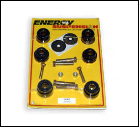 Fig 10. |
||
So
we are almost there, where have we been and what have we seen over the
last five articles. It makes you feel like Donald Pleasence in the Fantastic
Voyage. We have journeyed through the workings of various suspension
types. We have learnt some of the differences between the good old steering
box and the new fangled rack and pinion steering and now we have finally
traversed that mountain that is the chassis. Hopefully we all have a
better idea of how these various systems are put together, what problems
can occur and how to perform some simple maintenance should things go
wrong. So that’s it for now, see you next time when we shall be asking Martin’s 10 year old son how the internet works. |
||