


Performance
part 1 Classic American issue 185 |
|
|
|
Performance is attainable at so many levels; yes
we are talking about your car. You really need to decide what kind
of performance you want from your car and what you can realistically
expect to achieve on your particular budget. This month will take
a look at the heart of most people’s idea of performance; yes
you’ve got it, the motor. So before you begin to write your
shopping list for the finest performance goodies money can buy, it
would be prudent to check out what you already have. It is amazing
how many people buy cars and trucks without even finding out what
engine is in the vehicle, let alone what has already been done to
it. So before you start to play, find out what sort of motor you have
and if it has already been modified or is it still in its standard
form. It is also worth remembering to take into account things like
the axle ratio, tyre size and transmission when you are thinking of
modifying your motor. Time spent looking into these basics now will
be time well spent. Of course this should be done before talking to
your parts supplier. However, if you are unsure as to what you actually
require a conversation with your parts supplier will help you purchase
and fit the correct and compatible parts to give you the best results
for your money.
Firstly let’s check out the motor and its condition. If you do not ‘know’ your motor but believe it to be in its standard form, correct identification may be all that is required. This can usually be done before you dismantle the motor. Simply find the identification numbers on the block and heads and have them decoded. If you are unable to decode the information yourself, you can refer back to Classic American #158, which carried the technical information to help you do this. Checking head cast numbers as well as the block numbers can often show if the heads have been changed. If you find different heads on your motor this may or may not be a good thing. The heads may have been replaced as a performance option, hoping to gain valuable horsepower, but then they may have been changed because one or both were damaged at some time. If damage was the reason for the change then there is every chance the heads may be holding back and restricting the true potential of the motor. Bear in mind that the heads might be a poor match to the block. In the discussion that follows we are assuming that the motor is in good order or recently rebuilt, before we start placing more strain on it. If your motor is an unknown quantity then it’s your best guess as to its condition. Obviously there are pointers that can give us clues as to the overall condition of an unknown engine. Is the oil pressure good? Does the motor overheat easily? Does it smoke? Does the top end rattle? Does the bottom end knock? If the answer is yes to any of the above you may need to rebuild or rethink the whole performance thing. You really do not want to put time and money into a project only to have your best efforts go up in smoke, literally. Ok what sort of power do you require? Lots I here you shout! Well ambition is a great thing, but do remember that as the horsepower increases the reliability can decrease. Just remember that even the big boys of NASCAR that have a multi million dollar budget are hoping that their 800 horse power small block motor will finish one race before being stripped and rebuilt by the best professionals in the race industry. A good rule of thumb for reliable street performance is to attain up to one horse power per cubic inch, this is usually within the reliability factor and usually affordable. So the equation is if you have a 350 cubic inch motor its best to look for 300-350 horsepower. Many motors of this displacement may only be achieving a little under two hundred horsepower. This means there can easily be room for a one hundred plus horsepower increase depending on the year and model. Now as you can imagine one-hundred horse power or fifty- percent increase will be a very noticeable improvement when put into in practice. There are many manufacturers of performance parts and each of those manufacturers make hundreds of parts that can be used in various combinations to give just as many performance options. Obviously in an article like this we can only scratch the surface with some of the more popular parts and combinations that we have both installed and used or had reliable feedback on throughout the many years they have been in production. What we will do is try to take a look at some of the best-known brands and products on the market. When trying to squeeze every available ounce of power from an engine so many variables come into play. Things such as camshaft grind, compression ratio, valve diameters, inlet manifold, carburettor and exhaust system etc. We will try to cover some of the many variances and equations that add up to a better working, better performing and reliable motor in the following tech features. |
|
Right,
hopefully you have identified your engine, checked its condition, worked
out your budget and are happy to bolt on some performance. Without getting
too technical the camshaft and inlet manifold are a good place to start.
It is always a good idea to make sure that you match components. It’s
all to easy to buy the inlet manifold from a friend then get a ‘fifty
quid’ cam from the auto-jumble, only to find that they both perform
in different power bands and make you car perform worse than before
they were fitted. Also bear in mind that just because two items are
made by the same manufacturer, it does not always mean that they will
work well together. Let’s start with the camshaft. Many camshafts
are available as part of a camshaft and lifter kit, fig 1,
this is always worth consideration, as you must replace the lifters
when replacing the camshaft, (failure to do this will lead to premature
camshaft lobe failure). It should also be remembered that many manufacturers
do not give a warranty on camshafts that are not fitted with new lifters.
Most kits will come with lifter ‘break-in’ lube which again
is a must use item, fig 2. |
|
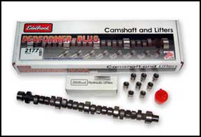 Fig 1. Camshaft and lifter kit |
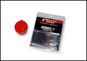 Fig 2. Camshaft ‘break-in’ lube |
Obviously
depending on what you want to achieve the camshaft should have sufficient
lift and duration to let your motor breath properly. The new camshaft
in fig 3 shows good lift and duration, as a comparison
the well used camshaft in fig 4 shows lobes that are
so worn that there is very little or no lift at all. The motor that
this camshaft was removed from would certainly have run very poorly
and suffered from severe power loss. Unfortunately finding a camshaft
in this condition is not uncommon. |
|
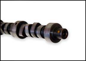 Fig 3. New camshaft |
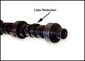 Fig 4. Worn lobes |
| The
camshaft duration is the amount of time that the cam allows the valve
to stay open either on the induction cycle or exhaust cycle. The lift
of the cam should also be checked, too high a lift may result in the
possibility of valve spring bind. Valve spring bind is caused when the
cam lift is so high that the valve spring is compressed too much and
the coils literally bind together. Needless to say this will very quickly
lead to bent or damaged components, just look at the push rods in fig
5 for example. The lift and duration specification of camshafts
will normally be available from your parts supplier who should be able
to recommend the correct camshaft for your particular motor and application.
Remember that a cam with too long a duration and or too high a lift
will more than likely result in a choppy idle. Chances are this will
make the vehicle very difficult to drive in a slower stop start everyday
situation. |
|
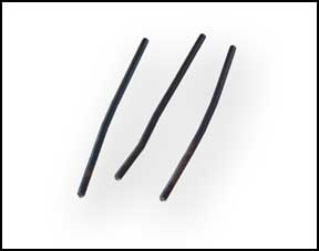 Fig 5. Bent push rods |
|
So
what does this tell us? You will need to look at the ‘power band’
that you want to achieve. The power band is the best performance operating
area, for a given scenario, i.e. street, street-strip, race etc…
The power band is usually given in rpm (revs per minute) this is the
amount of times the crankshaft makes one whole revolution in a minute.
For street use you would normally want the power band to start just
up from the vehicles idle, so for a street performance camshaft or inlet
manifold you may see its power band shown as: idle to 4000rpm. There
are many cams and inlet manifolds on the market giving very broad power
bands and our desired results are easily achievable. The ideal inlet
manifold to achieve this ‘off idle’ power band would be
a dual plane manifold. What? Another new term…Dual Plane? Let’s
see if we can explain what we mean by this. Well to start there are
many different types of inlet manifold for numerous applications. To
explain all the different variations would take many more pages than
we have here. For the power band, performance and economy we are looking
at for street performance it is best to ignore the very radical and
very specific race inlet manifolds and concentrate on the two main types
of manifold, these are single and dual planes. Let’s take a look
at the Edelbrock Performer dual plane manifold first, fig 6.
As suggested, the dual plane is simply the best option for low-end power
in a street use situation. This is due to the way in which the manifold
distributes the air / fuel mixture. The air / fuel mixture is distributed
by two main chambers positioned directly below the carburettor. This
is achieved by splitting the plenum area from side to side into two
distinct distribution areas positioned at slightly different heights,
fig 7, and folding the incoming flow of air / fuel.
|
|
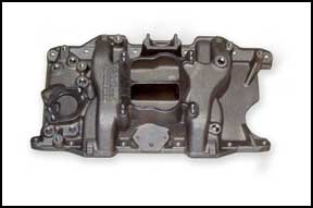 Fig 6. Performer dual plane |
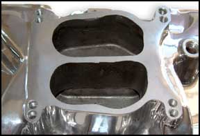 Fig 7. Split plenum heights |
This
mixture is then distributed along pathways called runners into the cylinder
heads ready for combustion. The runners are fed by the carburettor through
each half of the plenum. Thus one half of a four-barrel carburettor
would feed to each side of the manifold, acting like a two-barrel carburettor
for each cylinder head. This in turn can make it easier for fine tuning,
as you will know which half of the carburettor is feeding which chambers.
The Edelbrock Torker is a single plane or open plenum manifold, fig
8, which has as its name suggests an open chamber or plenum
below the carburettor where the fuel air mixture is introduced from
the carburettor and distributed to the cylinders, fig 9.
This style of inlet manifold is a successful design and very popular.
There is one drawback with this type of manifold as far as street use
is concerned. The power band will not be ‘off idle’ but
much higher, usually starting around 2000 to 2500rpm and upwards. This
shift in the power band is due to the air / fuel mixture from all venturies
of the carburettor effectively being dumping into one large chamber
and then being distributed to the cylinders. So whilst you would still
have a marked increase in power, it has been shifted up the rev range
and is only usable in a much narrower rev band. |
|
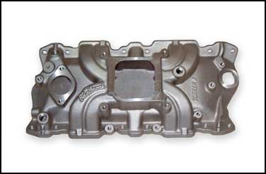 Fig 8. Edelbrock Torker |
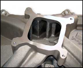 Fig 9. Open plenum |
Moving
on to the carburettor, this should obviously not only be suited to the
camshaft and inlet combination but also the displacement, or capacity
of the motor. Remember here that size is not everything and big is not
necessarily beautiful in the world of carburettors. An engine that is
over carburetted will lose lower end performance and economy over an
engine fitted with a carburettor of the correct size. So what are the
main differences with carburettors? Well in this situation we are looking
at four-barrel carburettors, which may or may not have a vacuum operated
secondary, this is the second half of the carburettor that opens the
second set of butterflies on a common shaft. This Holley 600cfm carburettor,
fig 10, can be driven at lower rpm’s with just
the two primary butterflies operating, fig 11, on a
common single shaft connected to the throttle pedal via a linkage or
cable. |
|
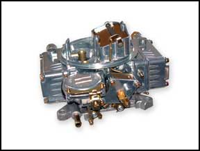 Fig 10. Holley 600cfm carburettor |
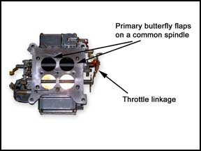 Fig 11. Primary butterflies |
This
is basically the same as driving with a small or two barrel carburettor,
but once the set rpm is reached the second half of the carburettor comes
into operation, fig 12, via a vacuum operated diaphragm,
fig 13, and more fuel / air can be delivered as required.
This type of operation means that performance can be delivered with
a reasonable amount of economy. |
|
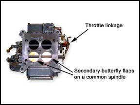 Fig 12. Secondary butterflies |
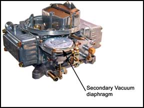 Fig 13. Vacuum operated diaphragm |
The
other main type of carburettor has a mechanically operated secondary
like the Edelbrock Performer 600cfm, fig 14. The mechanical
secondary type of carburettor, as its name suggests, has the second
half of the carburettor operated mechanically and opens in relationship
to the position of the accelerator pedal. Carburettors come in many
other flavours such as single and two-barrel, square flange, spread
bore and air-valve secondary, but these can be discussed in depth at
another time. A very simple rule of thumb for four-barrel carburettors
is that the vacuum secondary will give you good performance and good
economy whereas the mechanical secondary will give better performance
but rob some economy to achieve this. |
|
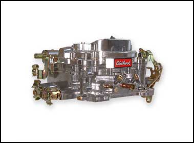 Fig 14. Edelbrock Performer with mechanical secondary |
|
That
all a side how do we find out which carburettor is best for your engine?
Well, carburettors come rated in units call ‘cfm’, cubic
feet per minute. This is the flow rate of the carburettor. You may have
heard people talking about 600cfm carbs or 750cfm carbs. As a good guide
for street use, we have found that a carburettor should flow at approximately
1.8cfm per 1cu.in of engine displacement. So, for example a 350cu.in
engine x 1.8cfm = 630cfm, approximately. So the best carburettor for
this application would be either a 600cfm or 650cfm carburettor. Please
remember that this equation is only given as an approximate guide for
street performance. There are a number of variables such as inlet, camshaft,
exhaust etc, which should also be taken into account if you are looking
for an exact figure. There are many books published that purely cover
carburettor types and choosing the correct one for your particular application.
Of course once you have fitted your new carburettor you can fine-tune
it with various jet sizes for increasing or decreasing fuel flow. Finally,
as long as space under the hood allows, you are able to finely tune
the carburettor and manifold and the rev range by the addition of spacers
under the carburettor, fig 15. |
|
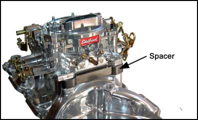 Fig 15. Carburettor to manifold spacer |
|
Spacers
are available in various thickness’, ranging from a few inches
down to ¼”, fig 16. These can have a marked
improvement on most applications, but do not over do it; again biggest
is necessarily the best. There is a trial and error element here and
you may find that going beyond ½” could have a detrimental
effect on your application. It could be worth considering a heat dissipater
/ spacer as these are made up of multiple layers so the height can be
varied, fig 17, with some fine tuning you can get some
great results for very little cost. |
|
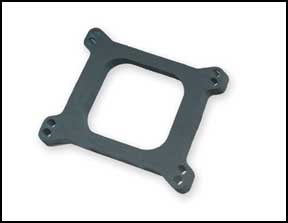 Fig 16. Open spacer |
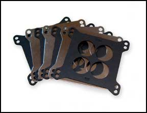 Fig 17. Multiple layer spacer |
|
|
So,
what have we learnt. Well, for those of you who are looking to perk
up the performance of your car or truck, consider looking at the cam,
inlet manifold and carburettor as a starting point. You can make some
very noticeable changes for relatively little cost. From this we know
that budget does play a big part in the options you have. However, we
have, of course, only scratched the surface of performance upgrades
here. There are, as we mentioned earlier, many other performance options
available, for example aluminium heads, roller rocker arms, forged pistons
and much, much more. We will be covering many of these aspects of tuning
and getting involved with the techniques and technicalities of performance
in future articles. |
|
|
|
|