


Bright Sparks Classic American issue189 |
||||
|
||||
How many of you have ever faced the following scenario. You are out driving at night enjoying the peace and quiet of the country roads when suddenly the headlamps on your muscle car are stolen! Or at least they might as well have been, because they have both failed without warning. This is an all too familiar scenario especially for owners of vehicles from the sixties through to the eighties. These niggling electrical problems are all too often brought about by ageing components such as the headlamp switches, which on some vehicles may have a circuit breaker incorporated within it. Other possibilities are incorrect components such as headlamps and, or fuses with the wrong rating or a mismatched lamp upgrade. If components have been replaced with parts rated at either too low or too higher wattage, systems may overload and cause circuit breakers to open, fuses to blow or in the worst case cause a small fire under the hood or under the dash. Of course if you were planning to cook out or have a roadside ‘Bar-B-Q’ this is not too much of a problem. However, if all you wanted to do was complete your journey, you’re in trouble. So this month we will mostly be looking at electrical problems, fault finding and hopefully showing you various ways to solve some of these problems. We will be looking at amps, watts, voltage and candlepower, and no this is not the power rating of the new Chevrolet Kalos engine. |
||||
Before
we go any further maybe we should just cover the differences between
fuses, circuit breakers and relays. Let’s begin with a brief look
at fuses. In electrical terms a fuse is basically a type of over-current
protection device. A fuses ‘critical component’, the part
that breaks, is usually a metal wire or strip that melts when heated
by a pre-determined electric current, this then opens the circuit of
which it is a part and so protects the circuit from damage. Properly
rated fuses are an essential part of a power distribution system. They
are used to prevent fire or damage due to overload or short-circuit.
An over-current device should normally be selected with a rating just
over the normal operating current of the downstream wiring or equipment,
which it is to protect. Fuses are often characterised as fast-blow or
slow-blow according to the time they take to respond to an overload.
For automotive use there are two basic types of fuse, the cartridge
fuse, fig 1, and the spade fuse, fig 2.
The cartridge fuse usually comes in three different lengths. Likewise
the spade fuse comes in three different physical sizes. Firstly the
mini-fuse which measures 10.9mm x 3.6mm x 16.3mm, next the ATO or ATC
fuse which measures 19.1mm x 5.1mm x 18.5mm and finally the maxi-fuse
which measures 29.2mm x 8.5mm x 34.3mm. |
||||
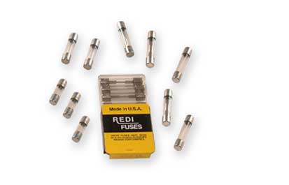 Fig. 1 |
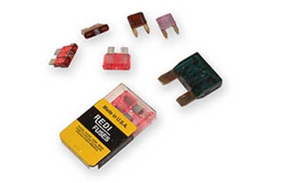 Fig. 2 |
|||
Next
let’s take a look at circuit breakers. These basically do the
same job as a fuse but can be reused. Most automotive applications use
what is known as an auto-reset compact circuit breaker, fig
3, although some applications do use a manual reset circuit
breaker. Most of these compact circuit breakers are designed to with
stand a direct overload but will trip, or open quickly on short circuits.
The circuit breaker will latch into the off position under fault conditions
and automatically resets to the on or closed position after a set period
of time. However, if the fault that caused the trip still exists, the
unit will immediately open again. This will continue until the fault
is put right. The only difference between these automatic circuit breakers
and the manual type, is the addition of a reset button on the manual
type. If a manual circuit breaker trips it must be closed by pressing
the reset button. In some situations it is possible to replace ATO or
ATC type fuses with a circuit breaker as long as there is room in the
fuse holder. Finally let’s go over the relay, fig 4. Whilst not technically an over-current device, relays play an important role in all automotive electrical circuits. In its simplest terms a relay is just an electrical switch. However, rather than being operated manually a relay switches under the control of another electrical circuit. In its most basic form, the switch is operated by an electromagnet to open or close one or many sets of contacts. Joseph Henry invented this basic type of relay in 1835. It is worth remembering that a relay is able to control an output circuit of higher power than the input circuit. For example the high current starter circuit on your vehicle is controlled using a circuit with a much lower current. |
||||
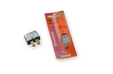 Fig. 3 |
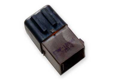 Fig. 4 |
|
||
If you are going
to seriously consider getting into fault finding it is almost essential
that you purchase a multi-meter, fig 5. Once you
have one of these you will quite simply wonder how you ever got by
without it. Even with the simplest meters you can carry out numerous
tests on resistance, voltage, amps and continuity.
Right, if your headlamps have gone out, how do we set about finding the problem? Well faultfinding needs to be carried out in a very logical manner. The first question we need to ask is: do they work all right if you turn them off and leave them for a while and then try them again? If the answer to this is yes then the chances are you have a problem with either a circuit breaker or a relay. If the answer is no then the system probably has a blown fuse or blown bulb or lamp. Initially let’s assume that we think the problem lies with a blown fuse or bulb. We shall begin by checking the fuse. We now need to locate the fuse box. If you have the vehicle’s handbook the location of the fuse box can usually be found here, or at leased a picture of it. In some handbooks and manuals the fuse box maybe referred to as an Electrical Power Distribution Centre. If you don’t have the handbook there are a few common places that vehicle manufacturers like to put the fuse box. Many are situated under the driver’s side of the dashboard or in the end of the dashboard to be found when the door is opened, fig 6. |
||||
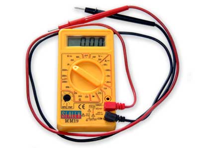 Fig. 5 |
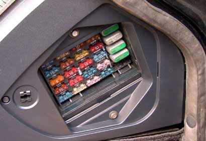 Fig. 6 |
|||
Many
newer cars and trucks will have a fuse box and an Electrical Power Distribution
Centre in the engine bay, fig 7. Once you have located
the fuse box and the fuse, check to see if the correct value fuse was
in place. The value of the fuse is usually marked on it. The correct
value for the fuse can then be found in the owner’s handbook.
Some fuse boxes also have the fuse values marked on them, fig
8. |
||||
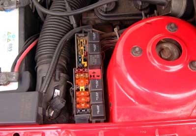 Fig. 7 |
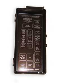 Fig. 8 |
|||
Obviously
too lower rated fuse will blow quickly because it cannot handle the
continuous demand. At the other extreme a fuse with too high a value
and it will not blow when the system has a problem, this in turn can
lead to hot or melting wire, blown bulbs or worse still, the inevitable
fire. If you are unable to see if the fuse is blown, you can use your
multi-meter to perform a simple continuity test. A blown fuse,
fig 9, should simply be replaced with a fuse of the correct
value. However, if the fuse was not blown put it back in the fuse box
and let us move on to the headlamps. It should be fairly clear to see if the lamp or bulb has blown, fig 10. |
||||
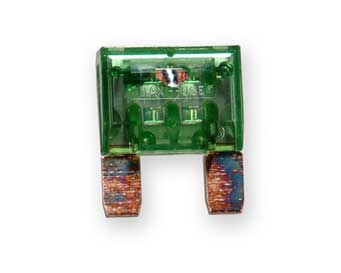 Fig. 9 |
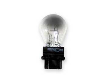 Fig. 10 |
|||
However,
if you are not sure you can use your meter to test the continuity of
the bulb, fig 11. Obviously if it’s blown simply
replace it with a bulb or lamp of the correct value and type. Just because
two bulbs look the same, it doesn’t always mean they are the same,
there are many different types of bulb, fig 12. Remember
that the cause of a blown bulb could have been a fuse of incorrect value.
Most standard headlamps and headlamp bulbs used are rated at approximately
55 watts for dipped and 60 watts for main beam. Usually the value is
marked on the back of the lamp or the base of the bulb, fig
13. You can obviously use this information to check whether
or not the lamps have been changed. As we have already mentioned, this
value will normally be given in watts, a measurement of electrical power.
Some light sources such as auxiliary lights or headlamps are rated in
different units other than watts, candlepower or candela are also common
units. To be able to compare different types of light sources, it would
be necessary to convert between these types of units when a rating of
both candlepower and watts is not given. So now the question is how
do you convert between candlepower and watts? Unfortunately the short
answer is, you cannot directly convert between these various units.
Unless the manufacturer of the lamp or bulb already has calculated both
candlepower and watts, you're pretty much out of luck. Watts and candlepower
are two very different measurements. |
||||
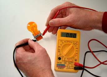 Fig. 11 |
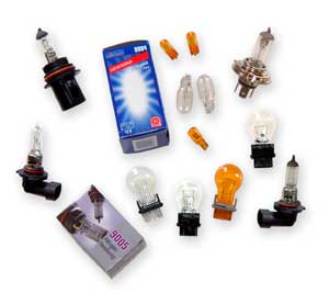 Fig. 12 |
|||
Let’s
just give you a brief explanation of what watts and candlepower are
and hopefully this will help to provide the reason. So for the number
crunchers amongst you, Watts is a measurement of the power needed, in
our case, to light the bulb to its best brightness. One watt is the
unit of electrical power equal to 1 amp under a pressure of 1 volt.
Amps are the rate at which electricity flows through a wire. A good
analogy is water flowing through plumbing. When you turn the tap on,
water flows out at a certain rate. The same thing occurs when you turn
on your headlamps. Remember that electricity flows at a certain rate,
this is amps. Watts are the amount of power a device uses in performing
its function. If for any reason you need to calculate the Amps, watts
or volts in a circuit there are a simple set of equations that can be
used. As long as you know two of the values you can always calculate
the third. Electric power is represented by the letter P in electrical
equations, and as we already know is measured in watts, named after
Scottish engineer James Watt. In resistive circuits, instantaneous electrical
power is calculated using Joules’s Law, which is named after the
British physicist James Joule, who first showed that electrical and
mechanical energy were interchangeable. Joule’s law gives us the
following equation P=IV where as already mentioned P=power, I=Current
measured in amps and V=potential difference measured in volts.
For example if you know
that the wattage of a bulb is 55W and the circuit is run on 12V we can
find the current draw using the following equation: I=P/V. Therefore
I=55/12, this gives I=4.583A. So we now know that each bulb draws 4.583
amps. Alternatively we might know that our headlamp circuit typically
draws 4.6A and is on a 12V circuit. Therefore P=IV giving us P=4.6x12
which results in P=55.2W. The higher the Wattage, the brighter the bulb
will be in use and it’s this rating that is generally used for
all incandescent lamps (ones with a filament). |
||||
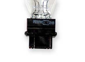 Fig. 13 |
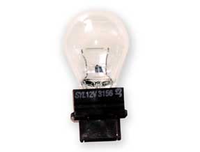 Fig. 14 |
|||
Now
where were we, oh yes, we have examined the headlamp or the bulb obviously
if it’s blown replace it with one of the same type and value.
Most bulbs and headlamps will have a part number on them, fig
14. On some bulbs this may be on the base on others it may
be printed or etched on the glass. It is worth making a note of this
number before you contact your supplier. If they ask for the number
at least you will have it to hand. Okay, so you have checked the fuse and checked the bulb, what if it is neither of these. Well there is a possibility that the problem lies in the actual wiring itself. So the next step is to make sure we have a voltage reading at the lamp’s socket. Again we can make use of our multi-meter. Set the meter to DC volts, probably best on the 20V scale, fig 15. This has been highlighted in our example. Now with the socket off the lamp or bulb turn on the headlamp switch and probe the socket with your muti-meter, fig 16. If your vehicle has a 12V battery you should see approximately a 12V reading on the meter. It is always worth trying to take this reading with the engine both off and running. The reasoning behind this is quite simple, if the voltage regulator on the alternator is failing or has failed this could be sending a high voltage through the system causing the bulbs to blow. So if you have a reading in excess of 14.5V it may be worth checking the vehicles alternator or voltage regulator for a fault. However, if the reading significantly lower than 12V then the problem probably lies with the battery or the wiring. Let us first of all check the wiring. Initially check the earthing of the system. Make sure all earth straps have a good clean connection and that they are secure |
||||
|
||||
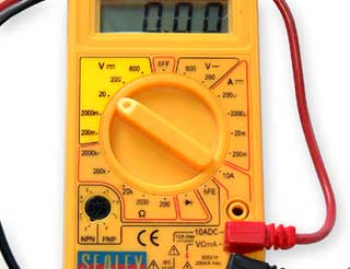 Fig. 15 |
|
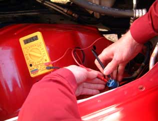 Fig. 16 |
||
Check
your battery terminals, making sure that these are also clean and secure,
fig 17. It is amazing how many electrical faults can
be traced back to a poor earth or loose battery terminals. With these
checks made, recheck the voltage at the lamp socket. If you still have
nothing reading on the meter, the chances are either the wiring has
a break in it somewhere or the headlamp switch is at fault. In tracing
a wire fault this can be a time consuming job. This can be done by checking
the continuity of various sections of the wire using the multi-meter.
However it is also worth checking the wiring visually. If all appears to be well with the wiring then there are only two real possibilities where the fault may now lie. Firstly the relay or secondly the headlamp switch. The easiest of these items to check is the relay. Once located you will need to turn on the headlamp switch and listen. You will be hoping to hear a click sound, this noise will be the relay activating. If you want to be completely thorough you may want to use your multi-meter to check the voltage in and out of the relay. If the relay is not activating the headlamp circuit this is obviously where the fault lies. Again the relay will have a number on it, copy it down in case your parts supplier asks for it. Should the relay check out as being okay, through a process of elimination and pure deductional genius, the fault must lie with the headlamp switch. Well at least we hope it does. Depending on the type of headlamp switch you have, it is either going to be very easy or very difficult to test. In all honesty we find it is rarely worth trying to remove and test headlamp switches. It is usually easiest to just replace the switch, fig 18, and be done with it. This is especially true if you have an older vehicle where, as mentioned earlier, the component may be suffering from old age. |
||||
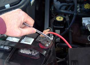 Fig 17 |
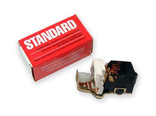 Fig. 18 |
|||
Hopefully we have
helped guide you through some basic electrical fault finding. In this
case on the headlamp system. However, it should be noted that the
basic principles of the fault finding remain the same whether you
are trying to find a fault with the headlamps, tail lamps or the interior
lamps. Some circuits may contain other components that may be at fault,
so be aware of this. For example, if you suspect a fault on the turn
signal or hazard circuits, you may have a flasher unit in the circuit,
which could be at fault. If you are having problems with your headlamps
not being bright enough, then there are plenty of upgrade options.
We shall endeavour to cover these in a later article.
Just as a final note, if you do not feel confident in carrying out any of the procedures mentioned in the article please make sure you get a qualified auto-electrician to carry out the work. Whilst we are talking about relatively low voltages that are not particularly life threatening, changing any components incorrectly may lead to an electrical fire. This of course maybe life threatening and will almost certainly mean the demise of part or all of your vehicle........always like to end on a high note. |
||||
|
||||