


Cooling part one Classic American issue192 |
||
|
||
At sometime or another
we all have experienced or are likely to experience the problems of
an overheating vehicle, it is almost inevitable. But why do our vehicles
get so hot that they feel the need to eject their coolant through
various orifices while cloaking the front of the car in a dank cloud
and leaving us stranded by the roadside? Is there anything we can
do to prevent these problems occurring? Are there any warning signs
to look out for that might indicate when a vehicle is going to overheat
or the cooling system is going to fail? Well, so many questions, and
over the next few articles we are hoping to shed some light on the
answers to these questions. However, before we start we really must
have some kind of understanding of the cooling system. Both, what
is the cooling system? And what makes up the cooling system? Once
we understand the basics we can then move on to working out why we
are likely to have problems. |
||
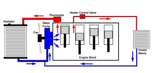 Fig. 1 |
A basic
liquid cooling system works by moving coolant, usually a mixture of
water and antifreeze, through the engine where heat is transferred from
the engine to the coolant, fig 1. The coolant then
passes to a radiator where the heat is transferred to the surrounding
air. Any cooling system must have enough cooling capacity to cool a
vehicle over any number of given driving conditions, be it heavy snow
or driving through mountainous regions at the height of summer. The
engine's temperature must be regulated in such away that it stays as
close as possible to the manufacturer's recommended running temperature.
This is usually around 93 degrees Centigrade (200 degrees Fahrenheit),
give or take 10 degrees Centigrade. Such regulation is maintained by
the vehicle's thermostat. |
|
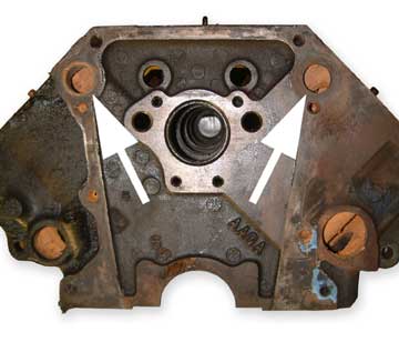
A water
pump, usually mounted on the front of the engine, sucks the cooled coolant
mixture from the radiator and pushes it into the engine’s waterways,
fig 2. As the coolant flows through the engine it absorbs
heat from the engine. When the engine reaches it’s operating temperature
the thermostat opens and allows the coolant to flow into the radiator
for cooling. Whilst the coolant passes through the radiator heat is
transferred to the tubes and fins of the radiator. This heat is then
transferred to the air that is flowing through the radiator. When the
vehicle is stationary or travelling at low speeds airflow is maintained
by either an electrical or belt driven fan. Obviously, at higher speeds
the relative velocity of the vehicle in relation to the outside air
maintains airflow. |
 usausausausausausauusausa Fig 2 |
|
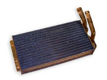
The
heating system of most vehicles is supplied by the cooling system. This
is done via a secondary and smaller cooling system that allows hot coolant
from the engine to pass through the heater core, fig 3,
in the passenger compartment. The coolant then flows back to the water
pump. However, instead of a thermostat controlling the flow of coolant
around this system, a separate valve called the heater control valve,
fig 4, facilitates the flow of coolant along this path.
|
||
 usausausausausausa..........Fig 3 |
 usausausausausaus............aFig 4 |
|
usausausausausa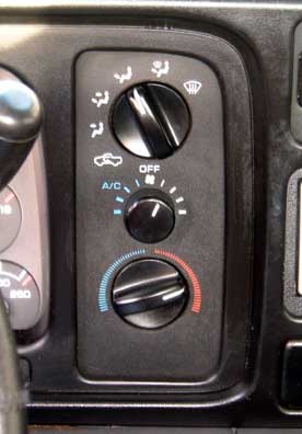 usausausausaususausaus..............aFig 5 |
The
heater control valve is in turn controlled by the lever or electronic
climate control on the dashboard, see fig 5, The opening
and closing of the engines thermostat does not restrict this part of
the system, so passengers get heat even when the thermostat is closed.
However, some vehicles have a mechanism that shuts off coolant through
the heater if the engine overheats. |
|
 usausausausausausaus......Fig 6 |
||
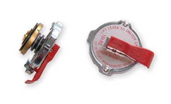
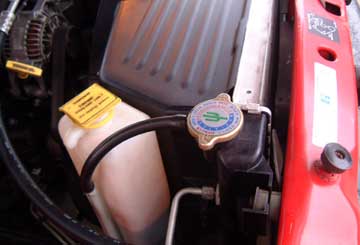
Most
cooling systems are closed or sealed with one or two usual exceptions,
the radiator cap and the expansion tank. The radiator cap should contain
a spring, fig 6, that helps maintain a constant pressure
by allowing the venting of coolant to the expansion tank, fig
7, when pressure rises above its specified value. |
||
Most
systems run at around 12-16 Pounds per Square Inch of pressure. This
is why the expansion tank usually contains more coolant when the engine
is hot than it does when it’s cold. This part of the system also
works in reverse and the cap allows coolant to be sucked back into the
system via a small hose from the expansion tank as the engine cools,
again as seen in fig7. Right, so now we have a good
idea of what the cooling system is, what it does and how it does it.
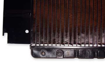
But what of the various parts that make up the cooling system. Well
possibly the most important part of the cooling system is the radiator.
The radiator core is normally made of aluminum or brass flattened tubes
with strips that weave between the tubes, fig 8. It
is these strips or fins that transfer the heat in the tubes into the
air stream to be carried away from the vehicle. On each end of the radiator
core is a tank, which on late vehicles may be made of plastic that covers
the ends of the radiator. On most modern radiators, the tubes run horizontally
with a plastic tank on either side. Other cars and trucks have the tubes
running vertically with the tank on the top and bottom. The majority
of older vehicles had radiators with a core made of copper and brass
tanks. However, the newer aluminum and plastic radiators are much more
efficient and cheaper to produce. Radiators with plastic end caps usually
have gaskets between the aluminum core and the plastic tanks, sealing
the system and preventing the coolant from leaking out. The older copper
and brass radiator tanks were soldered or brazed to seal the radiator.
These tanks, whether plastic or brass, each have a large hose connection,
one mounted towards the top of the radiator allowing the coolant in,
whilst the other is mounted towards the bottom of the radiator on the
other tank to let the coolant back out. It is usually the top of the
radiator that has an additional opening. This is used to fill the radiator
and is normally capped off by the radiator cap. |
||
 ...................................Fig 7 |
 .................................Fig 8 |
|
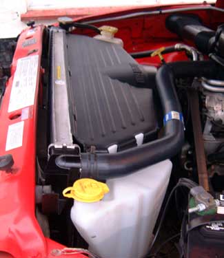
Some
radiators, on vehicles with an automatic transmission, have a separate
transmission oil cooler built in. Fittings on the end tanks connect
this cooler through steel tubes to the automatic transmission. Transmission
fluid is piped through this cooler allowing the transmission fluid to
be cooled before returning to the transmission. If the vehicle has air
conditioning, there is usually an additional radiator mounted in front
of the normal radiator. This is the air conditioning condenser. This
radiator also needs to be cooled by the airflow entering the engine
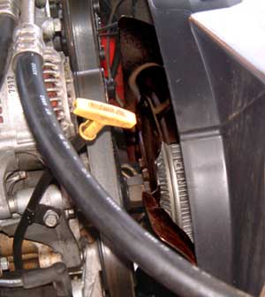
compartment. Regardless of how well heat is transferred to the radiator, unless you have good airflow at the radiator, the cooling system will not function correctly. As we mentioned earlier at higher driving speeds, air is forced through the radiator as the vehicle moves forward through the air and at these speeds a fan is redundant. Whilst at idle and low driving speeds, a fan is required to maintain airflow through the radiator. There are two main types of fan setup. These are mechanical fan systems, fig 9, or electric fan systems, fig 10. Note that transverse engines will usually have an electric fan system. This is because of the difficulty of having a drive belt turn through a right angle to operate a front-facing fan. However, it is becoming more and more common for vehicles with laterally mounted engines to also have electric fan setups. |
||
 .........................Fig 9 |
.................................Fig 10 |
|
Electric
fan systems normally consist of one or two fans mounted on the radiator.
They are usually mounted on the engine side. There will also be some
electronics, in the form of a sensor and switch, usually running through
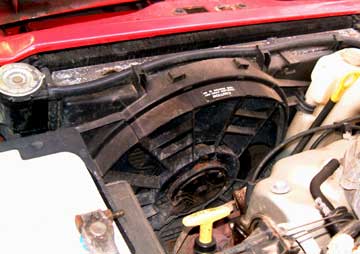
the vehicles computer, which will turn the fan on and off as required. A lot of vehicles with forward facing engines use a mechanical fan system; this consists of the fan, sometimes a fan clutch, fig 11, a fan belt, and radiator shroud, fig 12. On such a system the fan belt turns the fan clutch, which in turn turns the fan, which pulls air through the radiator, all of which is constrained by the radiator shroud. The fan shroud is more or less a tunnel between the fan and the radiator, it’s primary function is to make sure that all the air pulled by the fan comes through the radiator, rather than being sucked from the surrounding area. Without a fan shroud, idle and low speed overheating is more likely to occur. |
||
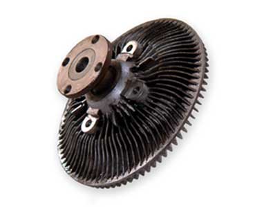 ............................................... Fig 11 |
 ..............................Fig 12 |
|
So
why is a fan shroud required for a mechanical system but is not a prerequisite
for an electrical system. Well as we have already said an electric fan
is mounted directly to the radiator itself. Therefore it is very close
to the radiator, and will actually move with the radiator. The chances
of it pulling air from anywhere other than through the radiator are
very slim. Contrast this with the mechanical fan, which is mounted,
in some cases, several inches away from the radiator. The mechanical
fan is mounted to and moves with the engine, and not with the radiator.
So installing a mechanical fan close enough to the radiator to eliminate
the need for the fan shroud would be almost impossible, without the
fan causing damage to the radiator when the engines torque causes the
engine to move. Obviously as the engine runs the coolant gets hot, and as it gets hot it expands. Since the cooling system is sealed, this expansion causes an increase in pressure within the system. This pressure increase is perfectly normal and is part of the design of the cooling system. When coolant is under pressure, the temperature where the liquid begins to boil is considerably higher. This pressure along with the higher boiling point of ethylene glycol (antifreeze) allows the coolant to safely reach temperatures in excess of 250 degrees Fahrenheit. The radiator cap simply helps to maintain pressure in the cooling system up to a certain point. If the pressure builds up higher than the predetermined pressure point, there is a spring-loaded valve, which is calibrated to the correct Pounds per Square Inch to release the pressure, and a small amount of coolant is bled off. When this happens there is a system in place to capture the released coolant. It is stored in a small translucent plastic tank in the engine bay. This tank is known as the expansion tank and is not usually pressurized. As the engine cools, a partial vacuum is generated, as there is less coolant in the system than at start up. The radiator cap has a secondary valve, which is designed to allow the vacuum in the cooling system to draw the coolant back into the radiator. There are usually markings on the side of the plastic tank marked Full-Cold, and Full-Hot. When the engine is at normal operating temperature, the coolant in the expansion tank should be visible at around the Full-Hot line. After the engine has been sitting for several hours and is cold to the touch, the coolant should be around the Full-Cold line. |
||
|
||
 usausausausausa............... Fig 13 |
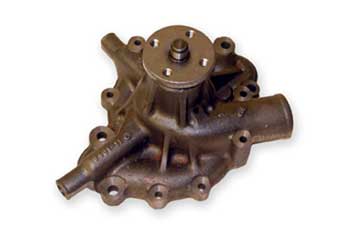
Next
to the radiator the water pump is an important part of the cooling system.
Automotive water pumps are usually simple devices that pump the coolant
around the engine and radiator. There are generally two types of water
pump, mechanical or electric. The mechanical type pump, in fig
13, is usually mounted on the front of the engine and turns
whenever the engine is running. It is driven by the engine through one
of the following: a fan belt, a serpentine belt, or it will be driven
by the timing belt that is also responsible for driving one or more
camshafts. |
|
The
water pump is made up of a housing, usually made of cast iron or cast
aluminum and an impeller mounted on a rotating shaft, a drive pulley
is usually attached to the shaft on the outside of the pump body. A
seal keeps fluid from leaking out of the pump housing past the spinning
shaft. The impeller uses centrifugal force to draw the coolant in from
the lower radiator hose and send it under pressure into the engine block.
There is a gasket to seal the water pump and prevent the flowing coolant
from leaking out where the pump is attached to the block. An electrical
water pump is basically the same as the mechanical pump but instead
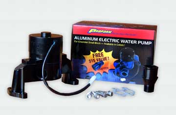
of being belt driven, as the name implies, it is electrically powered,
fig 14. |
 ................................Fig 14 |
|
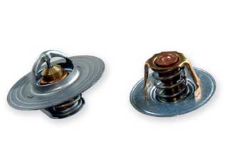
The
thermostat, fig 15, is a simple heat sensitive valve
that senses the coolant’s temperature and if it is hot enough,
opens to allow the coolant to flow through the radiator. However, should
the coolant not be hot enough, the coolant’s flow to the radiator
is blocked and coolant is feed to the bypass system. Because the coolant
temperature is not being reduced, the engine will reach operating temperature
sooner and, on a cold day, will allow the heater to begin supplying
hot air to the interior more quickly. Ever since the 1970s most thermostats
have been calibrated allowing them to keep the coolant around 192 to
195 degrees Fahrenheit. Prior to this thermostats were calibrated at
around 180 degrees Fahrenheit. It had been discovered that when an engine
is allowed to run at these higher temperatures, not only are emissions
reduced, but also any condensation inside the engine is quickly burned
off consequently extending the life of the engine. Fuel consumption
is also increased due to a more complete combustion of the fuel. At the heart of a thermostat is its sensor. This consists of a sealed copper cup that contains a metal pellet and wax. As the thermostat gets hotter the wax expands pushing a small piston against the spring to open the valve and allow coolant to circulate. The thermostat is normally situated at the front of the engine in the water outlet. This water outlet is also the connection point for the upper radiator hose. The water outlet is usually mounted to the engine using two bolts; a gasket is used to seal the water outlet to its mounting point. Most of the time the gasket is a heavy paper type, although rubber ‘O’ rings are becoming more and more popular, fig 16. |
||
 usausausausausaus.......Fig 15 |
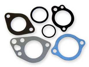 usausausausausausa....Fig 16 |
|
| This
bypass setup is a system by which the coolant is able to bypass the
radiator and go directly back to the engine. Depending on your vehicle
this bypass passage may be as simple as a rubber hose, or a fixed steel
tube. Other engines may well have a passage cast into the water pump
or front housing. So when the thermostat is closed, the coolant is directed
to this bypass and then sent back to the water pump. This then directs
the coolant back into the engine without being cooled by the radiator. When an engine block is manufactured, special sand is molded to the shape of the coolant passages in the engine block. This sand sculpture is positioned inside a mold and molten iron or aluminum is poured to form the engine block. Once the casting has cooled, the sand is loosened and removed through holes in the engine block casting leaving the passages that the coolant will flow through. These holes then need to be plugged or the coolant will pour out. This is where the core plugs come in. They are simply steel or brass discs or cups as seen in fig 17, that press fit in the holes in the side of the engine block. Steel core plugs do not last as long as brass plugs, they have a tendency to corrode. Replacing core plugs is a job that is either reasonably easy or extremely difficult depending on its location. Usual location for core plugs is the sides of the engine, usually 3 or 4 per side. Core plugs can also be found on the rear of the engine block and in the cylinder heads. Gaskets are not the first thing that spring to mind as component parts of a cooling system. However, all internal combustion engines require that the cylinder heads and manifolds be securely sealed to the engine block. This is in order to stop oil, coolant and combustion gases from leaking away. In order to seal these components together and prevent such leaks we use gaskets. It’s safe to say that the head gasket, fig 18, has the hardest job of all the gaskets, as it must seal in all the things we mentioned earlier, oil, coolant and combustion gases. A typical head gasket is usually made of a soft composite material that is stamped with ridges that surround all possible leak points. When the head is placed on the block, the head gasket is sandwiched between them. As the head bolts are tightened the head gasket is crushed and forms a tight seal between the two. |
||
usausa |
 usausausausausausa..........Fig 17 |
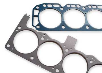 ..........................................Fig 18 |
There
are a number of rubber hoses that make up the plumbing of the cooling
system. These hoses connect the various component parts together allowing
the cooling system to function. The main hoses in the system are the
upper and lower radiator hoses. These two hoses are generally 1.25 to
2 inches in diameter and come in a variety of shapes depending on the
vehicle, fig 19. They allow the flow of coolant between
the engine and the radiator. Two smaller bore hoses, called heater hoses,
are used to supply hot coolant from the engine to the heater core. Normally
these hoses are between 0.625 and 0.75 inches internal diameter. A fifth
hose, called the bypass hose, may be used on some engine applications
as we have already discussed. These hoses are designed to withstand
the pressure and heat inside the cooling system. Because of this, they
are subject to wear and tear and eventually may require replacing as
part of routine maintenance. Finally there is usually a small rubber
hose that runs from the radiator neck to the expansion tank. This allows
coolant that is released by the pressure cap to be sent to the reserve
tank, as we have already discussed. This hose is about a quarter inch
in diameter and is not normally part of the pressurized system. |
||
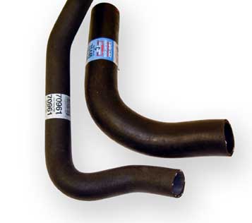 Fig 19 |
||
So
we now have a good idea of how the cooling system works and what, indeed,
makes it work. Next time we shall be moving on and looking at what problems
occur with the cooling system and why they occur, or the cause and causality
of problems. |
||